Follow the progress of construction (and sometimes destruction) of my N-scale model train layout.

January 28, 2007

Track Cleaning Woes

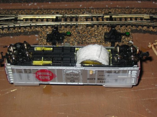
So I got my track cleaning assemebled and tried it out. It had some problems with the roller spinning freely. It tended not to roll and instead keep one area of itself in contact with the track resulting in the cleaning pad creating friction as it dragged along the rails isntead. I attributed this to poor quality: I think my axel hole through the center of the nickles was slightly off causing them to favor one side. I also think the axel holes in the sides of the car were not as accurately placed as they could be.

I tried to fix it by enlarging the axel holes in the side of the car, to no avail. I since the roller was dragging anyway I deceided to switch to a pad approach. I created a styrene base to support my cleaning pad (a paper towel) that rests on the rail. It is secured in the center of the car and has a small vertical range of motion. Combined with the angled edges, this helps it get over irregularities in the track.

This new approach seemed to work most of the time. The one thing that caused problems was trailing point turnouts. Occasionally, and on one turnout in particular, the cleaning pad got caught in the V formed by the converging tracks causing a stoppage. I am optimitic that this can be overcome by more securely attaching the cleaning pad since I was able to run the car with only the styrene base successfully.

No pictures this time. Maybe tommorow when I need a break from homework.

January 25, 2007

Cleaning Car II

I got styrene from the hobby store this weekend. Thick stuff, 0.04 inches. I started constructing my track cleaning car. I have it pretty much framed out and am waiting for the glue to dry before I put it on the tracks and see how it rides. I still have to drill the holes for the roller and add that in but I am anxious to see how it looks on the track since it is my first car from scratch. Hopefully pictures will follow tommorow of its maiden run.

Labels:

January 22, 2007

A down to earth layout

A 2.5 x 4 ft. N scale layout plan
In my last post I described a 2 x 8 ft. layout that will probably never fit in my apartment. Since I am probably going to be here for another year and a half I needed to come up with a more realistic plan if I was going to build a new layout.

So I came up with a modified version of my existing layout. I kept the thinks I liked and changed the things I didn't.

One the things that I discovered once I started operating my layout was the passing track / run around by the yard was too long. In reality this was never used as a passing track so it didn't have to be long enough to contain a full train. And even if it was, it was much longer then the typical 3 to 4 car trains that I would run. All this length means it takes longer to run around cars.

Another feature that didn't operate as intended was the switching lead /pocket. In my original plan it had been isolated from the rest of the track to allow a switcher to idle there while a road engine connected/disconnected from a cut of cars. This never happend since I forgot to include a place for the road power to idle while the switcher was working. It was also supposed to keep the switching operations off of the "running tracks". In reality I ended up using the passing side "running track" as the switch lead and the former lead was used as an interchange or special yard track. I also had problems with the two switches point to point in this area. This layout removes the lead and places a seperate interchange on the other side of the layout.

This layout also includes two engine storage track so I can run two engines without having to manually remove one from the layout. The sidings are also insolated so that engines can be parked in various locations while the other engine does a task.

As I mentioned before the interchange track was moved to the other side of the layout. It faces the oppisite direction from the two industrial sidings to add some variety. It also includes a short run around. This lets me operate trains in either direction without having to rely on the single huge passing track I had in my current layout.

Dream Layout

A 2 x 8 ft. N scale layout
After attempting to work in a solution to assemble bi-directional trains to my 5 x 1.5 ft. layout plan I was unhappy with the results. What I had originally intended to be a small staging area had grown into a mini yard. I was also realizing that I wanted to run trains in a loop so that I could simulate bi-directional traffic instead. The 5 x 1.5 size was becomming less attractive.

Fustrated by the size of my apartment I decided to design a larger layout that would incorporate the features that I wanted. Here is what I came up with. I decided to make my layout 2 x 8 ft. This would allow me to use 9 3/4 in. curves to create a loop. It was also narrow enough that I could place it up against a wall and not have to worry about adding in access points (even though I prefered the shorter 1.5 ft. maximum reach).

Other then the 180 degree curves and a industry siding, the layout uses broader 19 in. radius curves. It also uses #6 turnouts in the yard. These were done so that I could more comforataly use longer cars. My current fleet of freigh cars consists mainly of 40 ft. box cars. The 50 ft. cars that I have are starting to show a little bit of overhang on the sharp curves. While there are still 9 3/4 in. curves on this layout they are seperated by 6 ft. instead of only 2 ft. on my current layout. I am hoping that this makes them less dominant.

The switch to #6 turnouts was for reliablity. An article in Model Railroader had reccomended using the larger turnouts when pushing cuts of long cars.

Now that I think about it, extending the layout to 2.5 ft or 3.5 ft. to make room for 11 or 19 in. curves would have been nice. But I was planning to build the layout on two 2 x 4 ft. frames so that it could be moved without totally destroying it and I could use quarter sheets of plywood and 2 ft. sections of insulating foam when constructing the layout. That would have also let me run passenger trains. I will save that variation for another time.

The different power blocks are labled as follows:

  • A - Main Line

  • B - Yard Area

  • C - Switcher Pocket/Lead

  • D - Yard Tracks

  • E - Engine Storage

  • F - Industry

  • G - Industry

  • H - Industry

  • I - Industry

  • J - Interchange


While I don't plan to run two trains at once I do want to be able to have multiple engines on the layout. One engine can be parked on an industrial siding in the middle of a switching job, while I switch to another engine to move cars else where on the layout.

I blocked out as many blocks as I thought I could ever use. I will probably not wire them all up, but it is easier to add the insulated gaps now then at a later point in time. For example all the yard tracks and yard area ( B and D ) will most likely be operated as one block. But if at some point I decided that I want to have full trains be staged on the yard tracks I can add controls to isolate them easily.

January 15, 2007

Layout Blues

I ran into a problem with the new layout design. I realized that I could not assemble/disassemble trains with the engine last (the last to roll onto the traverser) from the yard side. I wanted to be able to have the train pull off the traverser on the industry side with the engine in the front to simulate it pulling into the industries. This requires that the engine is the last car on the traverser which means that I can't use the yard to assemble trains.

I need to include a run around track in the yard as well so that I can assemble and break down trains no matter what end the engine is at. Back to the drawing board.

Bad Couplers

Image showing the offsets between the couplers.
Yesterday I was running my trains and had a derailment. It occured on a transition from a straight section to a 9 3/4 in. curve was the site of the derailment. The GP at the head of the train had entered the curve, while the box car behind it was still on the straight section. The box car's front truck jumped the rail and the car uncoupled.


Further investigation revealed that it was the combonation of couplers that caused the derailment, specifically the body mounted coupler on my GP-50 and an truck mounted coupler upgraded to MTL couplers using MTL 1128 Coupler upgrade kit. The gP had a 6.5 cm wheelbase and a body size of 11 cm which gives the body mounted couplers a large arc. The long shank coupler on the GP normally provides enough lateral play to negotiate the sharp transistions with another normal coupler. However the converted coupler had a restricted range of lateral motion, practically zero. So this combonation caused both couplers had reached the limits of their lateral motion and began to apply lateral force against each other. This caused the truck of the box car to jump the rail.

The image with this post shows the two couplers in thier centered position at the position of the derailment. The space between the couplers give you an idea how much lateral motion is required to round the sharp curve.

This was not a problem with my other engine since it had a shorter wheel base and body ( 5 cm and 8.5 cm ) The other cars had factory installed couplers so they had enough lateral motion to negotiate the transition with the GP.

As a solution I tried to remount the couplers on the GP slighly closer to the wheels so that thier swing was reduced. This did not help. Since it is only the combonation of the one car and engine, it should be avoidable by not having them coupled while traversing the tight curves. It could also be eliminated by using easements and larger radii curves.

January 5, 2007

Layout

Diagram of the layout
Well I did some work and came up with another layout possiblity. Rather then focus on a mainline switching operation I switched to a terminal switching operation. This sovled the problem of having trains come from both directions. Two different entrance tracks provides give me a reason to have multiple roads servicing the terminal area.

The layout features a 12.5 in. traverser to transfer trains from the staging area in back to the two entrance tracks. It is just long enough to squeeze on a GP-60 engine and two 50 ft. cars. The traverser is the area in orange. It will only have one track, but all four positions are shown.

The dark grey boxes are buildings. The light grey box is a viaduct. I am not sure if it is for cars or trains yet. It helps to block the view of the traverser from the rest of the layout. The light blue box is a sky board or some sort of view block to hide the staging area at the top of the layout from view.

I blocked out the layout into 9 power blocks, four in the staging area and five on the main layout. That was one of my regrets from the first layout was not blocking out anything so that I had to swap engines on and off tracks manually. With this I can have multiple engines on the layout, even though I will only be running one at a time. I can park an engine on a siding, turn off the power to the siding, then have another engine come through to do some switching.

January 4, 2007

Track Cleaning Car

My track cleaning car on the tracks

Fed up with my engines stalling out I deciced to look at a track cleaning solution. I found one I liked. The Eliminator by Aztec, but at $60 it was a bit pricey. I decieded to build my own.

The first thing I did was hot glue togethor 6 nickles into 2 stacks of 3 each. I then drilled a hole in the center of both stacks that was large enough to fit a tooth pick into. I then put them both on a tooth pick seperated by a plastic washer. The washer gave me the spacing I needed as well as served as an insulator in case the roller ever came in contact with both rails. I topped this all off by cutting a strip of paper towel the same width as my roller and securing it with a drop of white glue.

To house the roller I took a old Bachmann 50 ft. box and removed the thin steel weight on the bottom. I cut out an hole in the bottom of the plastic frame big enough to fit the roller into. I left a little bit of the bottom frame on either side to connect the two trucks.

I drilled two holes in the sides of the box car body to serve as supports for my toothpick axel. They were offset slightly so that the roller was at an angle. This was done to provide the scrubbing action so that the roller does not simply roll along the tracks as another set of wheels. I found this bit of information on the track cleaning car page of Aztec's website. They were centered at a height that allowed the roller to just touch the top of the rail. I then elongated them vertically to give the roller a bit of play. This would allow it to stay in contact with the top of the rail even if the track moved up and down slightly.
The bottom of my track cleaning car

I assembled the bottom frame and the box car body. I placed the roller inside the body and aligned the axel holes before inserting the toothpick axel. I also placed a half ounce weight over each of the trucks. Otherwise the car was so light that it would derail if the roller encountered any resistance.

It definitely could use some improvement, however there was dirt on the roller after my trial run so is not totally ineffectual. The biggest problem was that the roller was too narrow. It worked ok on the straight sections but on the curved sections one slide would slip off the railhead and fall down onto the ties. Widening the roller requires removing the small sections of the frame body that connect the two trucks. To fix this a support structure the goes over the top of the roller is required to keep the trucks spaced correctly.

Also on my to do list is to add a magnet and a pipe cleaner brush to the other side of the car. But these modifications are easier to do and I will leave them until I have the roller problem fixed.

January 3, 2007

Possible Layouts

layout with internal traverser
layout with external cassette
layout with no traverser

Here are the three layouts I was considering. The first one uses a traverser contained inside the layout to move cars and engines from the staging area at the top to the main switching area below. The area serviced by the traverser is inside the orange box.

The second layout uses an external cassette to move the cars and engines from the staging area at the top to the switching area on the bottom.

The third layout connects the staging area to the switching area by turnouts. In this layout the staging area is at the bottom.

I don't know if any of these will be the final layout. I want to be able to have trains run on and off the layout at both ends so I simulate traffic comming from both directions. I had been trying to work in a 18 in. x 5 ft. area but I might have to change that. Possibly going to a 4 ft. x 2 ft. area and having a loop.