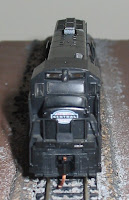
Follow the progress of construction (and sometimes destruction) of my N-scale model train layout.

November 23, 2007

Staging Control Panel

A while ago I constructed a staging yard on my old layout base. They sat under my bed for a while because I was waiting on switches to arrive so that I could control which tracks got power. The switches arrived, and the staging yard still sat under my bed. The staging yard saw its first trains tonight.

Earlier today I finally got around to installing the control panel and wiring up the staging yard. The above picture shows the staging yard hooked up to my layout, and taking up most of my bedroom.

The control panel is pictured above. It took a little improvising: the switches are held onto the styrene control panel with twisted wire due my lack of appropriatly sized screws. The holes above the switches are for LEDs to indicate which track has power. That part of the project is still on hold. I need to get properly sized resistors as well as figure out how the LEDs will get power. There are hookups between the old and new layout, the track power is transmitted via the rails.

November 7, 2007

Engine House Foundation

I did some more work on the foundation of the engine house over the weekend. I secured it to the layout and started to do some scenery around it. The yellow maintenance walkway also got attached as well.

The four white angle brackets match up with the inside of the engine house walls and allow it to be placed accurately on the layout since the doors don't have a large amount of extra space for clearance.

The one (suspected) problem with it is that at some points the styrene sheet may be slightly higher than the rail head. When I was constructing this the height difference seems immaterial as long as it looked good; however now after running engines over it I realize how close the truck side frames are to the level of the rail head. If the styrene is higher then the rail head then the truck side frame could ride up on the styrene and lift the wheel off the rail, causing the engine to lose power. Or maybe my track is dirty. I tried cleaning it but I have also tried cleaning sections of the layout where I have stalling problems before and it does not always seem to solve the problem.

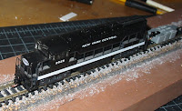
UB25 Coupler Conversion


I finally got my package with the Micro-trains conversion kit for my UB25 locomotive. It included a pair of what appeared to be the standard short shank couplers (formerly MT # 1015), however the package said they were the new reverse draft angle version "for improved pulling power", as well as a pair of pilot faces to cover the gaping holes where the truck mounted rapido couplers used to protrude.

The installation was fairly straight forward: Chop off the old rapido couplers. Smooth out the bottom of the deck where the pilot will be attached. Assemble the pilot and coupler. Glue pilot assembly in place to bottom of deck. The instructions stated that disassembly of the locomotive was not necessary, however I found it was much easier after the shell was removed from the frame.

The one peculiarity I found was that the screws appeared to be slightly too long for the pilot and protruded out of the top, which should have been flush for good contact with the bottom of the deck. They also provided shims which the diagram indicated should be mounted on the top of the coupler. I found this lowered the height of the coupler too much, however the shim helped to ease the screw overhang, so I ended up mounting the shim the bottom to help take up the excess screw height but not affect the coupler height.

Overall the conversion went much smoother then the conversion of my Bachmann GP-50 from scratch, even though the mechanics were similar. Not having to do the fabrication made it much easier. The molded details on the pilot face also make the UB25 conversion look better.