Upgraded Couplers for a Bachmann GP-50
A while ago I purchased a Bachmann GP-50. Much cheaper then the Atlas counter-part, but it also lacks some of the finer the details and knuckle couplers. I decided that I would improve it.
One task was to convert it to knuckle style couplers. My first attempt used Micro-Trains Line 1128 Universal Short Length T-Shank Coupler conversion kit. This kit uses an insert inside the Rapido coupler pocket to hold the knuckle T-shank coupler. This met with moderate success on the long hood end. The coupler was a bit further recessed underneath the body then I would have liked but it was still able to be operated with a pick.
However on the short hood end this approach did not work. The coupler was recessed too far underneath the body to be operated with a pick. One solution would have been to use a coupler with a longer shank, but I decided to switch to body mounted couplers. This would give me an opportunity to eliminate the void hole between the bottom of the walkway and the rails in the front. This had been required to allow the coupler to swing back and forth and the trucks turned.
For the conversion I used Micro-Trains Line 1015/16 Body Mount Coupler. While I was at the store I also picked up a coupler height gauge (Micro-Trains Line 1055).
- I removed the Rapido coupler and mounting arm by cutting off the mounting arm flush with the truck. This gave me plenty of clearance for the body mounted coupler.
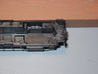 Since the bottom of the walkway was too high to mount the coupler (as determined by the car underbody function of the coupler height gauge), I needed to create a surface of the appropriate height to mount the coupler. The goal was to create a level surface to work with. This involved clearing away some of the plastic on the underside of deck. Mostly the holes that held the catches for the hand rails. I left the portion of the bulkhead that forms the edges of the stairs intact.
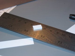
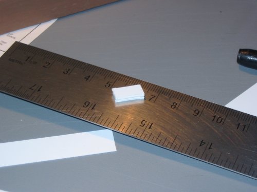
The next part was getting this surface to the correct height. I did this by gluing together 8 pieces of 0.25 mm styrene. The pieces were 12 x 6 mm. This block when placed underneath the deck, was the correct height for the coupler to be mounted on. This block sits flush up against the back of the forward bulkhead.
One consideration is to increase the length of the sheets once the height of the bulkhead has been reached. This way the block is flush with the front of the forward bulkhead and provides a larger surface area to mount the front panel on. It also gives more clearance between the hole for mounting the coupler and the front of the block.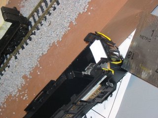 I attached the block to the body with plastic cement. If you don't have a drill bit that can do this you might want to hold off on this step and read ahead before cementing the block in place.
- After the block had dried in place, you need to drill a hole and attach the coupler. I didn't have a drill bit that was small enough so I used the point of a #11 Xacto knife blade to make a small hole. I had to do this on both sides of the block to make it deep enough without making it too wide. I also had to make a slight hole in the bottom of deck since the mounting screw protrudes slightly from the block when fully inserted. Needless to say I did not have a tap either, but luckily the screw was able to take hold and stay. Otherwise I would have applied some more plastic cement to bond the coupler draft box to the mounting block.
 At this point I checked the coupler against the height gauge again. Everything looked good and so my first body mounted coupler is complete.


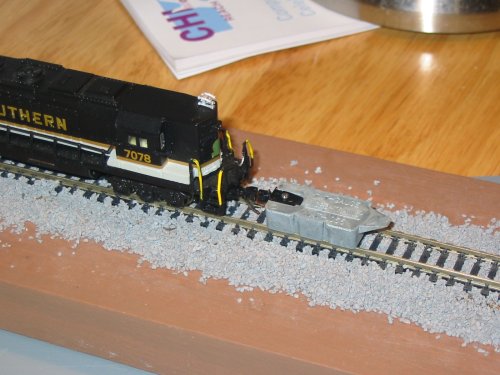
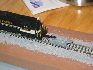
 I still need to convert the long hood end coupler to a body mounted coupler. Right now it is still a truck mounted coupler. I also need to fabricate a front panel to cover up the area where the coupler used to swing back and forth. You can see how it is very open looking in the image on the right. But those are projects for another day.
posted by Mark at
9:48 PM
![]()

0 Comments:
Post a Comment
Subscribe to Post Comments [Atom]
<< Home